Setting Up a Simple Layer 3 VPN
You want to set up a Layer 3 VPN for a customer who wants a private network for internal network communication and transactions.
Creating a Layer VPN for the customer involves setting up your PE and P routers. The customer (or you) can set up the customer’s routers (the CE routers). The PE and P routers must run an IGP, IBGP, MPLS, and a signaling protocol (RSVP or LDP). You establish an MPLS LSP between the PE routers and configure the VPN itself on the PE routers.
As a first step, set up the routing protocols necessary for the Layer 3 VPN. The PE and P routers must be running an IGP (this recipe uses OSPF). Following is the configuration for one of the PE routers, RouterB:
source@RouterB# set ospf traffic-engineering
On the PE router, enable MPLS and RSVP on the interfaces that connect to the P router:
source@RouterB# set rsvp interface so-0/0/0
Also, remember to configure family mpls on all interfaces between the PE and P router that carry MPLS and RSVP:
source@RouterB# set so-0/0/0 unit 0 family mpls
The IGP, MPLS, and RSVP configuration for the other PE router, RouterY, and for the P router, RouterH, is the same, substituting the appropriate interface names.
On each PE router, set up an IBGP session to the other PE router. For PE RouterB, the following commands set up the session:
source@RouterB# set family inet-vpn unicast
Include the equivalent configuration on the other PE router, RouterY:
source@RouterY# set family inet-vpn unicast
The second step is to create an MPLS LSP between the two PE routers to carry the VPN traffic. On RouterB, configure the LSP to RouterY:
source@RouterB# set label-switched-path RouterB-PE-to-RouterY-PE to 192.168.50.1
Remember that LSPs are unidirectional, so on RouterY, which is the far-end PE router, configure a return LSP to RouterB:
source@RouterY# set label-switched-path RouterY-PE-to-RouterB-PE to 192.168.20.1
The third and final step is to configure the VPN itself. You do this by creating a routing instance for the VPN. The following commands configure the routing instance on RouterB:
source@RouterB# set routing-options static route 192.168.10.1/32 next-hop ge-1/0/0
This diagram shows how to configure a simple Layer 3 VPN for the network topology shown in Figure 15-1. In this network, a service provider connects two customer sites, Site A and Site B, with a VPN. The service provider network consists of two PE routers, RouterB and RouterY, and one internal router (the P router), RouterH. At Site A, RouterB connects to the customer’s CE router, RouterA. At Site B, RouterY connects to the customer’s CE router, RouterX.
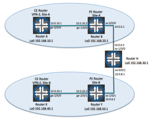
Simple Layer 3 VPN topology
Let’s start by looking at what the service provider needs to do to support the customer’s VPN. For the VPN to work, you first need to configure basic routing and signaling protocols within the service provider network. An IGP must be running on the network. This recipe uses OSPF, but you can also use IS-IS (see Recipe 11.1) or RIP (see Recipe 10.1). Use the show ospf interface, show ospf neighbor, and show route table inet.0 commands to make sure that the OSPF configuration in this recipe is working as expected.
For PE RouterB, these commands confirm that OSPF is operational and that the router is learning routes from OSPF:
10.0.0.2 so-0/0/0.0 Full 192.168.30.1 128 39
MultiRecv
The JUNOS software carries the VPN traffic across an MPLS LSP between the two PE routers. For the VPN to establish itself, MPLS and a signaling protocol must be running on all interfaces participating in the LSP. This recipe uses RSVP for signaling, but you can also use LDP (see Recipe 14.1). Check on each router to verify that MPLS and RSVP are running on the expected interfaces. The following commands confirm this on RouterB:
so-0/0/0.0 Up <none>
so-0/0/0.0 Up 1 100% 1.536Mbps 1.536Mbps 0bps 0bps
One last protocol that you need to set up on the PE routers is BGP. These routers need to be connected by an IBGP session that will exchange VPN routing information. Here’s the IBGP configuration on PE RouterB:
source@RouterB# set family inet-vpn unicast
In the set neighbor command, use the loopback address of the other PE router, even though that router is not immediately adjacent. Here, 192.168.50.1 is the loopback address of RouterY. The set family inet-vpn unicast statement identifies that the session is for a VPN. Configure the other PE router, RouterY, in the same way.
Use the show bgp summary command to verify that the IBGP session is up:
Table Tot Paths Act Paths Suppressed History Damp State Pending
bgp.l3vpn.0: 0/0/0
The first line of the output shows that RouterB is in one BGP group and has one peer, and the State column in the Peer section tells you that the IBGP session is established. However, instead of the unicast routing table inet.0, the IBGP session is using the bgp.l3vpn.0 routing table, which stores the routes learned from other PE routers. Let’s look at the contents of this table:
source@RouterB>
How come there aren’t any entries in this table? It’s because we haven’t yet configured the VPN itself, so the PE routers are not exchanging VPN-related routes. We’ll come back and look at this routing table in a little while.
The show bgp neighbor command also indicates that the IBGP session has been established:
Output Queue[0]: 0
The first two lines of the output show the peer’s IP address, which is RouterY’s address, and that the IBGP session is established. The Address families configured line shows that this interface can process VPN-IPv4 addresses (inet-vpn-unicast). Further down in the output, you see information about the bgp.l3vpn.0 routing table.
The VPN traffic between the two sites will be carried over an MPLS LSP. In the second part of the configuration, create this LSP on the two PE routers with the set label-switched-path commands. Use the show mpls lsp command to verify that the LSP is functional. Here, we check on RouterB:
Total 1 displayed, Up 1, Down 0
Total 1 displayed, Up 1, Down 0
Total 0 displayed, Up 0, Down 0
The output shows what you expect. RouterB has one ingress LSP session, to RouterY, and one egress session, from RouterY.
At this point, you are ready to set up the VPN itself. Each VPN requires its own routing instance so that all information related to one VPN and its routing can be isolated from other routing and forwarding and from other VPNs that the router is managing. The set instance-type vrf command indicates the routing instance as being for a VPN and that its routes will be placed in the VRF routing table.
All routes that are part of the VPN are identified by a route distinguisher, which you define with the set route-distinguisher command:
source@RouterB# set route-distinguisher 65500:02
You can specify the route distinguisher in two ways. This recipe uses the AS number followed by a colon and an identifying value. You can also use an IP address followed by a colon and an identifying value. Neither format is better than the other. The format you choose depends entirely on your design and specific requirements. Using the IP address:value format allows you to identify the originating PE router when you are looking at a route and its communities, because you normally set the IP portion to the PE router’s lo0 address. This format can assist with troubleshooting and operational monitoring. Using the AS:value format has the advantage of leaving more space for the Administrator variable (four bytes instead of two bytes). Service providers often choose this second format, using the value field to hold a numeric customer identifier. When looking at routes, this format makes it possible, on a network-wide basis, to identify the customer associated with a route.
For the VPN to know which routes belong to it, you define a VRF target using the set vrf-target command:
source@RouterB# set vrf-target target:65520:100
The command sets the route target (the target VPN), which is one of the BGP extended community attributes. The VRF target identifies which route belongs to which VPN and allows the VPN to accept routes into its VRF routing table and to advertise them.
The set vrf-target command also associates a default import and export policy with the VRF routing table to accept and advertise routes. The default policy uses the configured target, here 65520:100, as the match condition for routes received from remote PE routers. As the import policy states, any routes containing this target are placed into the VRF table. Similarly, when sending routes to local PE routers, the export policy is for the VPN to advertise any routes matching this target. The default routing policy is a simple policy that would look something like this if you configured it manually:
source@RouterB# set community VPN2 members target:65500:2
source@RouterB# set term 2 then reject
source@RouterB# set term 2 then reject
If you need more involved policies, configure them in the [edit policy-options] hierarchy and apply them to the VPN with the set vrf-import and set vrf-export commands, specifying the name of your policy. As an example, the following commands apply the VPN2-import-policy and VPN2-export-policy policies to VPN2.
Finally, the VPN needs to know how to forward traffic to the CE router at the customer site. This recipe creates a static route to use for forwarding:
source@RouterB# set routing-options static route 192.168.10.1/32 next-hop ge-1/0/0
You can also use BGP, OSPF, or RIP.
Now let’s verify that the VPN is operational. First, check that you can ping the CE router:
5 packets transmitted, 0 packets received, 100% packet loss
Why does the ping transmission fail if the static route is in the routing table? Let’s check the routing tables using a different command:
> to 172.19.121.1 via fe-0/0/0.0
> via ge-1/0/0.0
This command shows that the static route is present in the VPN2.inet.0 routing table but not in the inet.0 routing table. To ping it, you need to specify the VPN routing instance in the ping command:
round-trip min/avg/max/stddev = 10.346/21.011/40.311/11.186 ms
The ping operation now succeeds, and you have verified that static routing between PE RouterB and CE RouterA is working.
Let’s take a moment and look back at the IBGP session between the two PE routers. When you first configured it, the session was up, but the router had not learned any routes from BGP because the VPN itself was not yet up. Now that the VPN is up, you expect to see BGP routes. Use the show bgp summary command on PE RouterB:
VPN2.inet.0: 2/2/0
The last two lines show the two VPN-specific routing tables, bgp.l3vpn.0 and VPN2.inet.0 (the VRF table), both with BGP routes. Each table has two active routes and has received two routes. Recipe 15.2 explains how to view the contents of these routing tables.