Juniper VPN Configuration for two Customer

  • by

Adding a VPN for a Second Customer

You want to configure a single PE router to keep the traffic for the two different VPNs separated.

Configure the VPN for the second customer on the PE router:

[edit  
routing-instances VPN1 ]
source@RouterB# set instance-type vrf 
source@RouterB# set interface ge-3/0/0 
source@RouterB# set route-distinguisher 65500:1 
source@RouterB# set vrf-target target:65530:200 
source@RouterB# set routing-options protocols bgp group VPN1-group type external 
source@RouterB# set routing-options protocols bgp group VPN1-group peer-as 65530 

source@RouterB# set routing-options protocols bgp group VPN1-group neighbor 10.0.40.1

Have the customer configure an EBGP session on her CE router that connects to your PE router:

[edit protocols bgp group to-ISP ]
source@RouterC# set type external 
source@RouterC# set peer-as 65500 

source@RouterC# set neighbor 10.0.40.2

From a service provider point of view, the whole point of Layer 3 VPNs is to allow a single edge router in your network to provide services to a number of different customers and to isolate each customer’s network so that all information pertaining to it remains private. When configuring the PE router, you set up the router to keep each customer’s routing information in separate routing tables and you establish unique route distinguishers so that the PE routers can identify which routes belong to which VPNs.

This recipe shows how to add a VPN called VPN1 for a second customer. Figure 15-2 shows the network topology with both customers’ VPNs.

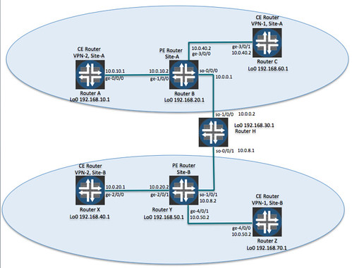
                        Layer 3 VPNs for two customers

Configuring the VPN for the second customer is somewhat simpler than for the first customer. An IGP, MPLS, and RSVP are already up and running on the PE and P routers, and the LSP between the two PE routers is already operational. What remains to be done is to configure the VPN itself. This VPN, named VPN1, connects to the CE routers using BGP rather than static routes. The following commands set the basic properties of VPN1:

[edit routing-instances VPN1 ]
source@RouterB# set instance-type vrf 
source@RouterB# set interface ge-3/0/0 
source@RouterB# set route-distinguisher 65500:1 

source@RouterB# set vrf-target target:65530:200

The first command defines the routing instance type, which must be vrf for Layer 3 VPNs. The PE router connects to the CE router using interface ge-3/0/0. Each VPN must use a different route distinguisher and VRF target. VPN1 has a route distinguisher of 65500:1 and a VRF target of 65530:200. The VRF target attached to a route shows the VPN to which a route belongs.

Next, configure the EBGP session to the CE router. You do this within the VPN routing instance, not in the [edit protocols bgp] configuration hierarchy, because you are creating an instance of BGP that the JUNOS software associates with the VPN. The configuration commands in this recipe are also used to create a regular EBGP session, but they are included within the VPN at the [edit routing-instance VPN1 protocols bgp] hierarchy level. Here’s what the completed configuration looks like on the router:

source@RouterB> show configuration routing-instances VPN1
instance-type vrf;
interface ge-3/0/0.0;
route-distinguisher 65500:1;
vrf-target target:65530:200;
protocols {
    bgp {
        group VPN1-group {
             type external;
             peer-as 65530;
             neighbor 10.0.40.1;
        }
    }

}

The BGP configuration establishes an external (EBGP) session with the neighbor 10.0.40.1 (the interface address of the CE router) that is in AS 65530.

For the VPN to work, the customer controlling the CE router, must establish an EBGP session with the PE router. On the CE router, the customer sets up a regular BGP session, configured at the [edit protocols bgp] hierarchy (see Recipe 13.1) and not part of a routing instance. Here’s what the configuration on the CE router in this recipe looks like:

source@RouterC> show configuration interfaces ge-3/0/0
unit 0 {
    family inet {
         address 10.0.40.1/24;
    }

}

source@RouterC> show configuration routing-options
router-id 192.168.60.1;

autonomous-system 65530;

source@RouterC> show configuration protocols
bgp {
    group to-ISP {
         type external;
         peer-as 65500;
         neighbor 10.0.40.2;
    }

}

As a first step in verifying the configuration, make sure that the EBGP session between the PE and CE routers is established. Check on the CE router:

source@RouterC> show bgp summary
Groups: 1 Peers: 1 Down peers: 0
Table          Tot Paths  Act Paths Suppressed    History Damp State    Pending
inet.0                 1          1          0          0          0          0
Peer               AS      InPkt    OutPkt    OutQ    Flaps Last Up/Dwn State|#A
ctive/Received/Damped…
10.0.40.2        65500         69        69       0        1      33:25  1/1/0

              0/0/0

The CE router has one BGP session to 10.0.40.2, the PE router. This is a regular EBGP session, and routes are placed in the inet.0 unicast routing table.

Checking on the PE router shows the BGP neighbors:

source@RouterB> show bgp summary
Groups: 2 Peers: 2 Down peers: 0
Table          Tot Paths  Act Paths  Suppressed   History Damp State    Pending
bgp.l3vpn.0            3          3           0         0    0                0
Peer               AS      InPkt      OutPkt   OutQ   Flaps Last Up/Dwn State|#A
ctive/Received/Damped…
192.168.50.1    65500      23091       23102      0       0      1w1d0h Establ
  bgp.l3vpn.0: 3/3/0
  VPN1.inet.0: 1/1/0
  VPN2.inet.0: 2/2/0
10.0.40.1        65530         46          49      0       0      22:36 Establ

  VPN1.inet.0: 0/0/0

The last entry shows that the EBGP session to 10.0.40.1, the CE router, is established and that its routes are in the VPN1.inet.0 routing table.

VPN1 also has a CE router (RouterZ) at the remote site that is connected to the remote PE router, RouterY. You configure these two routers the same way as the two routers shown in this recipe. Here’s the VPN1 routing-instance configuration on the remote PE router, RouterY:

source@RouterY> show configuration routing-instances
VPN1 {
     instance-type vrf;
     interface ge-4/0/1.0;
     route-distinguisher 65500:4;
     vrf-target target:65530:200;
     routing-options {
         static {
             route 192.168.70.1/32 next-hop ge-4/0/1.0;
         }
     }

}

Now check the routing tables on the PE router. First, let’s look at the VRF table for VPN1, which is VPN1.inet.0:

source@RouterB> show route table VPN1.inet.0
VPN1.inet.0: 4 destinations, 4 routes (4 active, 0 holddown, 0 hidden)
+ = Active Route, – = Last Active, * = Both
10.0.40.0/24        *[Direct/0] 00:42:02
                    > via ge-3/0/0.0
10.0.40.2/32        *[Local/0] 00:42:02
                      Local via ge-3/0/0.0
10.0.50.0/24       *[BGP/170] 00:07:11, localpref 100, from 192.168.50.1
                      AS path: I
                    > via so-0/0/0.0, label-switched-path RouterB-PE-to-RouterY-PE
192.168.70.1/32    *[BGP/170] 00:07:11, localpref 100, from 192.168.50.1
                      AS path: I

                    > via so-0/0/0.0, label-switched-path RouterB-PE-to-RouterY-PE

This table stores the routes for VPN1:

10.0.40.0/24 and 10.0.40.2/32 are the routes to the CE router, RouterC.

10.0.50.0/24 is the subnet to the remote VPN1 CE router (RouterZ), which has a router address of 192.168.70.1/32.

If the VPN1.inet.0 table truly isolates the routes for VPN1 so they are not visible to other VPNs or routers on the network, you expect that these routes are not in any of the other routing tables. To verify this, look at the other routing tables on the PE router. Here is the inet.0 unicast routing table:

source@RouterB> show route table inet.0
inet.0: 8 destinations, 9 routes (8 active, 0 holddown, 0 hidden)
+ = Active Route, – = Last Active, * = Both
0.0.0.0/0          *[Static/5] 2w1d 04:49:05
                    > to 172.19.121.1 via fe-0/0/0.0
10.0.0.0/24        *[Direct/0] 1w2d 10:18:57
                    > via so-0/0/0.0
                    [OSPF/10] 01:25:29, metric 65
                    > via so-0/0/0.0
10.0.0.1/32        *[Local/0] 1w2d 10:24:36
                       Local via so-0/0/0.0
10.0.8.0/24        *[OSPF/10] 01:25:29, metric 66
                    > via so-0/0/0.0
192.168.50.1/32    *[OSPF/10] 01:25:29, metric 66
                    > via so-0/0/0.0
192.168.30.1/32    *[OSPF/10] 01:25:29, metric 65
                    > via so-0/0/0.0
192.168.20.1/32    *[Direct/0] 1w2d 10:24:36
                    > via lo0.0
224.0.0.5/32       *[OSPF/10] 1w1d 04:30:18, metric 1

                      MultiRecv

This table has no knowledge of the 10.0.40.1/24 or 10.0.50.1/24 subnets, nor does it know about the two VPN1 CE routers, 192.168.60.1 and 192.168.70.1.

The VPN2 routing table also knows nothing about these prefixes:

source@RouterB> show route table VPN2.inet.0
VPN2.inet.0: 5 destinations, 5 routes (5 active, 0 holddown, 0 hidden)
+ = Active Route, – = Last Active, * = Both
10.0.10.0/24       *[Direct/0] 6d 09:24:16
                    > via ge-1/0/0.0
10.0.10.2/32       *[Local/0] 6d 09:24:18
                      Local via ge-1/0/0.0
10.0.20.0/24       *[BGP/170] 01:35:08, localpref 100, from 192.168.50.1
                      AS path: I
                    > via so-0/0/0.0, label-switched-path RouterB-PE-to-RouterY-PE
192.168.10.1/32    *[Static/5] 6d 09:24:16
                    > via ge-1/0/0.0
192.168.40.1/32    *[BGP/170] 01:35:08, localpref 100, from 192.168.50.1
                      AS path: I

                    > via so-0/0/0.0, label-switched-path RouterB-PE-to-RouterY-PE

A shortcut to verify that the VPN1 routes are only in the VPN1.inet.0 table is to look for routes to a prefix that you know is in this table:

source@RouterB> show route 10.0.40.1
inet.0: 10 destinations, 11 routes (10 active, 0 holddown, 0 hidden)
+ = Active Route, – = Last Active, * = Both
0.0.0.0/0          *[Static/5] 2w1d 04:58:17

                    > to 172.19.121.1 via fe-0/0/0.0

VPN1.inet.0: 3 destinations, 3 routes (3 active, 0 holddown, 0 hidden)
+ = Active Route, – = Last Active, * = Both
10.0.40.0/24        *[Direct/0] 01:36:31

                    > via ge-3/0/0.0

This output confirms that the route to the VPN1 subnet to the CE RouterC is present only in the VPN1.inet.0 table. The inet.0 table has no information about this route and uses the default route to try to reach it.

Next, check the bgp.l3vpn.0 routing table, which stores the routes received from other PE routers:

source@RouterB> show route table bgp.l3vpn.0
bgp.l3vpn.0: 4 destinations, 4 routes (4 active, 0 holddown, 0 hidden)
+ = Active Route, – = Last Active, * = Both
65500:3:10.0.20.0/24
                   *[BGP/170] 04:31:02, localpref 100, from 192.168.50.1
                      AS path: I
                    > via so-0/0/0.0, label-switched-path RouterB-PE-to-RouterY-PE
65500:3:192.168.40.1/32
                   *[BGP/170] 04:31:02, localpref 100, from 192.168.50.1
                      AS path: I
                    > via so-0/0/0.0, label-switched-path RouterB-PE-to-RouterY-PE
65500:4:10.0.50.0/24
                   *[BGP/170] 00:07:20, localpref 100, from 192.168.50.1
                      AS path: I
                    > via so-0/0/0.0, label-switched-path RouterB-PE-to-RouterY-PE
65500:4:192.168.70.1/32
                   *[BGP/170] 00:07:20, localpref 100, from 192.168.50.1
                      AS path: I

                    > via so-0/0/0.0, label-switched-path RouterB-PE-to-RouterY-PE

The PE router is now receiving routes from the remote PE router for both VPNs. The routes for VPN1 use the route distinguisher 65500:4, and the second two routes in the bgp.l3vpn.0 table are for VPN1. The first route, for IP prefix 10.0.50.0/24, is the subnet between the remote PE and CE routers, and the second route is to the CE router itself. These two prefixes match those contained in the VPN1.inet.0 table. The other two routes in the bgp.l3vpn.0 table use the route distinguisher 65500:3, which is for VPN2.

Let’s also look at all the routing tables on the CE router to see what they contain:

source@RouterC> show route
inet.0: 5 destinations, 5 routes (5 active, 0 holddown, 0 hidden)
+ = Active Route, – = Last Active, * = Both
0.0.0.0/0          *[Static/5] 8w3d 04:25:38
                    > to 172.19.121.1 via fe-0/0/0.0
10.0.40.0/24        *[Direct/0] 1w0d 03:12:18
                    > via ge-3/0/0.0
10.0.40.1/32        *[Local/0] 1w0d 03:12:18
                      Local via ge-3/0/0.0
10.0.50.0/24       *[BGP/170] 01:39:35, localpref 100
                      AS path: 65500 I
                    > to 10.0.40.2 via ge-3/0/0.0
192.168.60.1/32    *[Direct/0] 1w0d 03:12:18
                    > via lo0.0
__juniper_private1__.inet.0: 2 destinations, 2 routes (2 active, 0 holddown, 0 h
idden)
+ = Active Route, – = Last Active, * = Both
10.0.0.1/32        *[Direct/0] 8w3d 04:26:16
                    > via lo0.16385
10.0.0.16/32       *[Direct/0] 8w3d 04:26:16

                    > via lo0.16385

What you see here is that the CE router is just a regular router. The only routing table it has is the inet.0 unicast routing table (and the private inet.0 table that is used internally by the JUNOS software). The CE router has no knowledge of the VPN. It has a route to the PE router using the prefix 10.0.40.0/24. [Direct/0], which indicates that the CE router is directly connected to the PE router. The CE router also has a route to the subnet between the remote PE router and the remote PE router, 10.0.50.0/24, which it learned from its EBGP session with PE RouterB. It’s important to note that the CE router does not have any prefixes to reach any of the routers in VPN2. There is no prefix for CE RouterA (router address 192.168.10.1, on subnet 10.0.10.0/24), which is directly connected to PE RouterB, and there is no prefix to the remote VPN2 CE RouterX (address 192.168.40.1, subnet 10.0.20.0/24).

Just to make sure that prefixes are not leaking between VPNs, look at the routing tables on the VPN2 CE RouterA:

source@RouterA> show route
inet.0: 4 destinations, 4 routes (4 active, 0 holddown, 0 hidden)
+ = Active Route, – = Last Active, * = Both
0.0.0.0/0          *[Static/5] 2w1d 03:29:26
                    > to 172.19.121.1 via fe-0/0/0.0
10.0.10.0/24       *[Direct/0] 6d 10:05:34
                    > via ge-0/0/0.0
10.0.10.1/32       *[Local/0] 2w1d 03:29:28
                      Local via ge-0/0/0.0
192.168.10.1/32    *[Direct/0] 1w0d 08:31:19
                    > via lo0.0
__juniper_private1__.inet.0: 2 destinations, 2 routes (2 active, 0 holddown, 0 hidden)
+ = Active Route, – = Last Active, * = Both
10.0.0.1/32        *[Direct/0] 2w1d 03:29:53
                    > via lo0.16385
10.0.0.16/32       *[Direct/0] 2w1d 03:29:53

                    > via lo0.16385

The router has prefixes to reach the PE router (over the subnet 10.0.10.0/24) but has no knowledge of the VPN1 CE router, RouterC.

Leave a Reply